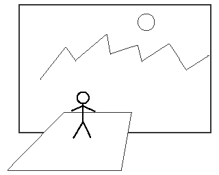
VR seems complicated with multiple screens and stereo, but in the end it simplifies down to calculating one projection onto one screen. Once you can do that correctly, the rest is just repetition.
A first and important step is to decide whether you are displaying a third person or first person view, where the user is looking at the 3D scene or is inside it respectively. Third person is appropriate for some modelling/design applications. First person creates a much stronger sense of immersion and is usual for VR systems. The downside is that it requires physically accurate view calculations. From now on I'll assume first person view.
A stereo view requires two projections, one for the left eye and one for the right. In an active stereo system (quad-buffered) there is a single monitor output, which alternates between left eye and right eye views. In a passive polarised system there are two monitor outputs projected onto a single screen, one for the left eye, one for the right.
The best model for thinking about VR view calculations is the magic carpet model. Think of the user as standing on a magic carpet. They navigate through your 3D scene by moving the carpet, or viewpoint in the OpenGL ModelView coordinate system, around. The display shows the scene from the current carpet viewpoint. This kind of navigation is usual in all 3D applications, whether desktop or VR.

In some VR systems the user can physically move around, without actually touching the 3D navigation controls, and the display will update to match. In our model, this is represented by the user changing position on the magic carpet itself. Or more accurately, the user's head changes position, and to detect this the computer must use some form of head tracking. For maximum accuracy, the position being tracked should be the midpoint between the two eyes.
Not all VR systems use head tracking, only those with screens that are physically fixed in one place. With a headmount display the screens always move with the eyes, so there is no head tracking, only viewpoint movement. Without head tracking the user is assumed to be fixed at a default head position throughout.
The ModelView viewpoint or digital camera location, for a single rendering of the 3D scene (on a screen directly in front of the user - we'll discuss multiple screens later) is therefore the accumulation of two 3D position & orientation values, 1. the magic carpet viewpoint, the traditional 3D navigation "where am I" value; and 2 the head position, which is often fixed.
To create the proper immersive illusion of virtual reality, the projection onto the screen must be identical to what the user would see if it were a real 3D scene. Think of the screen as a pane of glass through which the 3D world is being viewed. This means we have to work with the real world dimensions and locations of the screen and viewer, and that the 3D scene must use real world coordinates as well. Even if you are displaying the galaxy or a molecule, think of it as a real-world model and use an appropriate scaling transformations at the top of your scene graph to convert the internal units into metres.
These physical coordinates will also be used for head tracking. This is the layout of the Wedge dual screen stereoscopic display here at ANU in the coordinate system used by my VR programs:
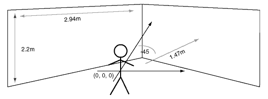
The coordinate origin is where the user stands, facing straight forward along the depth axis. It is not on the floor, but half way up each screen. The display area of each screen is 2.94m wide and 2.2m high. Both screens are 1.47 metres away from the origin, measuring along a line perpendicular to the screen itself, and are rotated by either 45 or -45 degrees horizontally. You'll find all these numbers in the simple text file listed earlier. (HPR is heading-pitch-roll angles, or euler angles, another way to express 3D rotations.)
For desktop systems accuracy is not essential, so the program can just choose reasonable defaults: say 0.4m wide and 0.3m high, viewed from a distance of 0.5m or so.
Stereo views always use asymmetric view volumes, or frustums. This means you can't use convenience routines like gluPerspective to set the OpenGL Projection matrix, but have to use glFrustum and calculate the view volume edges explicitly.
For stereo on a single screen, without head tracking, the left and right eye views are rendered by shifting the apex of the viewing frustum left or right by the eye separation distance. This gives two overlapping views of the same 3D scene. (There's another technique called 'toe in' or 'converging gaze' stereo which rotates the view axes for the left and right eyes instead. Don't do this. It doesn't work for any scene with objects beyond the convergence point.) Viewed from above, the frustums look like this:
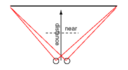
The parameters we need are the width of the screen, the distance of the user's head position from the screen, the left and right eye offsets, and the near clipping plane distance. (For this simple case we assume the user's head is at the origin, or centred, relative to the screen.) The horizontal edges of the view frustum are half the width of the screen plus or minus the eye offset distance.
  left edge  = -(width/2) - eye offset
  right edge = (width/2) - eye offset
(You may see different expressions in actual VR code, but they all end up calculating these values.) The eye offset is negative for the left eye, positive for the right. If the eye offset is zero, the result is a standard mono view frustum. In addition, because the frustum edges are specified at the near clipping plane, we need to scale these values by the ratio near / distance before passing them to OpenGL. (It would be possible to set the near clip plane equal to the distance from the screen, but this greatly reduces the immersive VR effect because nothing 'jumps out' from the screen at the user.)
With head tracking, the view frustums become more asymmetric. We need the head position as an extra parameter. Here are two different pairs of frustums for two different head positions:
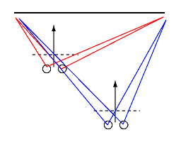
Since the default head position is centred at (0, 0, 0), these new frustum values can be calculated by adding the head position:
  left edge  = -(width/2) - eye offset - head.x
  right edge = (width/2) - eye offset - head.x
Note that if the head never moves from the origin, this gives the same values as for the simpler case above. We can therefore use this single calculation for all desktop, non-stereo, and stereo displays.
The near clipping plane is relative to the head position, not the screen, so the scaling value for the frustum edges will vary as the head moves forward or back. Lastly, regardless of what the user actually does, we always assume that the eye gaze direction is perpendicular to the screen. This is because all current 3D systems render the scene for a perpendicular view axis and cannot handle oblique projections. It's not physically accurate, but usually makes no difference.
Head movement can also change the vertical shape of the viewing frustum, but the calculations are the same as for the horizontal edges so not repeated here.
With multiple screen VR systems such as the Wedge we just repeat the stereo frustum projections for each in turn, with the added complication that we must factor in the rotation of the screen. In the diagram below, the small cross indicates the head position in the physical coordinate system and the green and red segments show how the left and right screen frustum pairs would be calculated. (Viewed from above.)
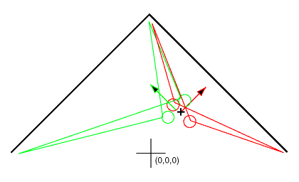
We calculate the view frustums as if the eye gaze was perpendicular to the screen, which obviously isn't the case for the Wedge where they are both rotated by 45 degrees. The first step is therefore to transform the head position into a screen-relative coordinate frame. I use an inverse transformation matrix derived from the screen position and orientation values in the config file; others use mathematically equivalent vector operations. You will also find minor variations from system to system in how the eye offsets are factored in. The outcome is always a head position and eye offset values which can be plugged in to the calculation given in the section above.
We also need to account for the screen rotation in the ModelView viewpoint or digital cameral location, otherwise both screens would display the same image. This adds two more factors to the calculation of the 3D ModelView viewpoint:
This has been a long explanation, because there are a lot of details that must be taken care of. Even so, I've simplified in places and you should read the code of an actual implementation to fully understand what is going on. The good news is that once you get it right, the code works without change for every new VR application you develop.
Next:Communicating with trackers
Back to 3D Graphics